


引言
高场固体核磁共振(Nuclear Magnetic Resonance,NMR)技术因具备无损、可定量、检测迅速、分辨率较高等优点,目前已在无机、有机、高分子和生物大分子材料研究中得到广泛应用[1].高速魔角旋转技术(Magic Angle Spinning,MAS)是获取固体高分辨率NMR谱的必要条件,然而,对于一些顺磁性样品(如三元锂电池等[2]),在高场条件下由于强顺磁干扰将出现磁场不均匀、谱线展宽、信号衰减、无法魔角旋转等一系列问题,难以获取有用的信息.由于顺磁样品的各向同性和各向异性相互作用都受到顺磁位移相互作用的影响,在谱图上往往表现为自旋边带叠加,从而导致特征峰无法分辨,严重影响谱图获取及解析.在低场条件下,由于磁场强度显著降低,将极大地弱化洛伦兹力和各向异性展宽效应,顺磁性样品的上述问题将不再是限制条件,不仅能正常魔角旋转,还能避免谱图旋转边带的叠加,在获得更好谱图分辨率的同时,可通过多次累加来弥补低场导致的信噪比损失,使得在低场下对顺磁样品体系的观测成为了可能[3-4].
低场NMR系统通过采用Halbach永磁体可显著降低设备成本并实现紧凑化设计,为开发桌面式固体NMR波谱仪提供了重要技术路径.然而,针对顺磁材料的低场固体MAS探头研制仍面临多重技术挑战:一方面,Halbach磁体有限的孔径要求MAS单元(含转子、驱动组件及射频线圈)实现高度小型化设计;另一方面,低场条件下信噪比急剧下降,需通过优化射频电路阻抗匹配与Q值等方式进行提升;除此之外,稳定的高速MAS需求进一步增加了技术复杂性.因此,开发适配紧凑型Halbach永磁体的固体MAS探头对推动桌面式低场固体MAS谱仪系统实现至关重要[5-
国内外关于低场固体MAS探头的研究较少,主要集中在固体高场谱仪或高场MAS技术的研究. 2014年,Sorensen等人[8]首次提出永磁体与MAS技术联用方案,证实低场条件可有效抑制化学位移各向异性,但其研究聚焦于高场NMR的辅助补充,未解决顺磁干扰核心问题.2022年,Klug等人[9]在500 MHz谱仪中发现,顺磁样品在33 kHz转速下虽可观测信号,但边带峰干扰显著;当转速降至12.5 kHz时信号完全湮没于边带峰中导致难以分辨,说明了高场MAS对顺磁体系的固有局限性.2023年,Xu等人[10]基于3D打印技术开发锥型MAS单元,初步实现桌面低场固体NMR系统,但受限于3D打印结构强度问题,锥型转子存在使用寿命不足、填充因子较低等缺陷.因此,现有工作多集中于高场MAS技术优化或低场原型验证,缺乏针对顺磁材料特性与低场条件兼容性的系统性设计.
为验证在低场条件下对顺磁样品体系测试的影响,本文基于自主研制的0.5 T 43 mm孔径Halbach磁体设计并研制了一套低场固体MAS探头,设计方案基于小型化MAS单元结构设计、气动驱动优化及射频线圈参数调控等技术.探头转子直径为4 mm,可实现14 kHz高速魔角旋转,能够对1H和7Li核进行固体NMR检测.将探头与谱仪控制单元、磁体单元、气路控制单元等组成了一套低场固体MAS谱仪,在该谱仪上进行了NMR性能测试,实现了对顺磁样品LiMn2O4、LiCoO2、Li3PO4和LiFePO4的高分辨率检测,验证了自主研制低场固体MAS探头在低场下对顺磁样品进行固体高分辨率NMR采集的可行性,为锂电池材料等顺磁体系的结构解析提供了新思路.
1 原理与分析
在固体NMR中,静态分子因偶极耦合(Dipole-dipole Coupling,DD)和化学位移各向异性(Chemical Shift Anisotropy,CSA)的强取向依赖性,导致谱线展宽远超各向同性化学位移范围,严重阻碍高分辨率信息的获取.MAS技术通过使样品绕与静磁场B0成54.74˚(即魔角)的轴高速旋转,利用动态平均效应消除一阶各向异性项,从而显著窄化谱线.然而,受二阶及以上哈密顿残余项的影响,MAS的平均效果通常不完全,此时魔角转速成为抑制高阶项的关键参数,需满足魔角转速大于各向异性相互作用强度时,才能有效压缩残留展宽[11-
在高场下对顺磁样品开展NMR研究的限制主要体现在以下3个方面:
(1)MAS稳定性与磁场不均匀性
尽管理想均匀磁场中(
(2)旋转边带增强与重叠现象
当魔角转速低于CSA相互作用时,在距离各向同性峰间隔整数倍旋转速率处会产生旋转边带峰.其中,CSA调制产生的旋转边带强度正比于
此外,旋转边带的位置与主磁场强度及转速密切相关,其数学关系可表述为:
(3)高场NMR放电现象的干扰
在高场环境下,部分导电样品旋转时会因感应电动势产生磁场,导致主磁场的极度不均匀,样品切割磁感线从而影响旋转,甚至与超导磁体发生互感,破坏磁体.若处于低场环境,样品产生的感应电动势和磁场强度会显著降低,主磁场的均匀性得到改善,切割磁感线的效应减弱,旋转受限或转速低的问题得到缓解[17].
因此,低场条件下可以通过弱化洛伦兹力F与CSA,显著降低技术实现难度.但也面临信噪比下降的固有缺陷(
2 探头设计方案
2.1 总体方案
图1
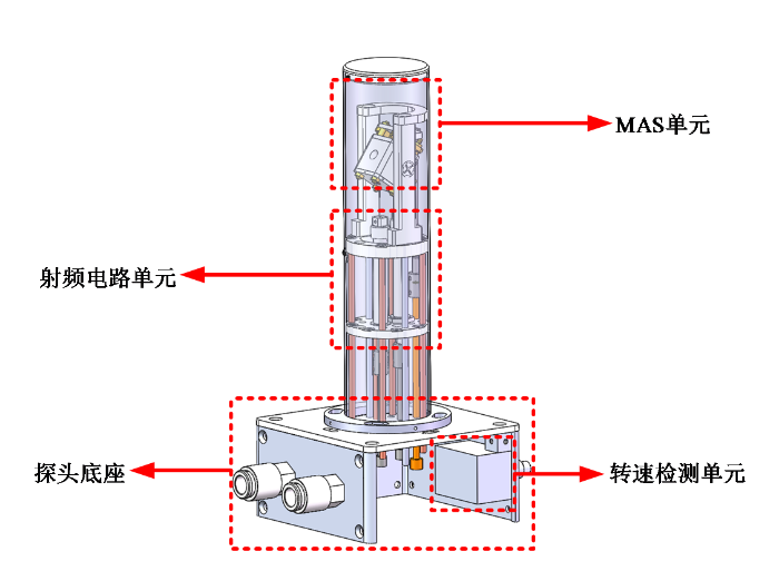
图1
低场固体MAS探头结构整体示意图
Fig. 1
Overall schematic diagram of low-field solid-state MAS probe structure
其中,MAS单元是低场固体MAS探头的核心结构,为样品魔角旋转提供了稳定而可靠的机械平台;射频电路单元作为探头射频信号发射与接收的重要模块,包括射频线圈及相应的调谐匹配电路;探头底座则为探头提供了必要的接口,如:射频接口、气路接口等.
2.2 MAS单元结构及小型化设计
MAS单元由MAS转子与MAS定子组成[19].MAS转子包含转子主体与涡轮端盖,承担样品装载与高速旋转功能,其中转子主体采用氧化锆陶瓷材料精密研磨加工而成,涡轮则采用精密五轴机床对聚酰亚胺材料进行加工;目前MAS转子构型主要可以依照转子形状分为:圆柱型MAS转子、锥型MAS转子[20,21]与球型MAS转子[22,23].其中圆柱型MAS转子因其MAS定子采用双径向轴承的设计使得转子在旋转时更具稳定性,并且相比于其它构型的MAS转子具有更优的填充因子,故本文采用圆柱型MAS转子的方案设计,基于此设计了配套的MAS定子.MAS定子由高精度定子主体、气浮轴承组(轴向轴承、径向轴承)与驱动装置组成,其中定子主体作为气路与支撑基体,通过螺杆与各部件连接固定,并通过多路气路接口连通气浮轴承组与驱动装置.
通过对各个零件进行三维建模与装配优化,确保装配的可行性.同时,为了满足Halbach磁体的小口径的需求,对传统的MAS探头进行了小型化设计.结合MAS单元的流体仿真优化,最终完成MAS单元的小型化设计,其结构设计图如图2所示.
图2

图2
小型化MAS单元结构设计图
Fig. 2
Schematic diagram of the miniaturized MAS unit structure design
图2中位于MAS单元顶部的定子上盖的驱动装置核心位置由六个沿涡轮切向的节流孔组成,气流通过节流孔提速后作用于涡轮上,驱动涡轮旋转;涡轮与转子通过过盈配合相连接,将动力传递至转子,驱动转子跟随涡轮旋转;位于转子上下侧的径向轴承,包含八个气孔,将气源输入的气压均匀分散至八个气孔,在轴承内圈形成气膜,并通过与轴向轴承的共同作用,使转子悬浮;径向轴承采用过盈配合与定子主体装配,保证了气路的气密性;定子主体是MAS单元的主体支撑结构,提供了MAS定子各个零件的装配位置、轴承及驱动的气路通道、与低场固体MAS探头相连接的气路接口及支撑接口、线圈模块接口等.
此外,为保证气源所提供的压力气体能顺利到达轴承与驱动装置,避免在传输过程中发生压力损耗或泄露,同时还要保证流入轴承及驱动的气体能顺利排出到大气中,避免积压在MAS单元内部产生乱流,需要进行气路设计.其中,驱动气体通过图2中的驱动气路进入驱动装置节流孔作用于涡轮上,轴承气体通过轴承气路进入轴向轴承及径向轴承,经过轴承的节流孔节流后作用于MAS转子上.
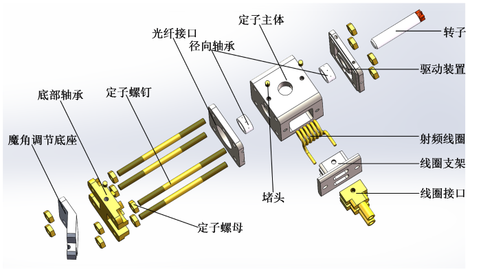
图3为小型化MAS单元的三维爆炸视图,图中列出了MAS单元所需的所有零件三维结构模型,包括转子、驱动装置、径向轴承、定子主体、光纤接口、底部轴承与魔角调节底座,以及用于装配的定子螺钉、定子螺母和堵头.
图3
为了验证小型化后MAS单元的气路驱动能力,使用仿真软件对MAS单元的驱动气路进行有限元仿真.涡轮动力装置有6个直径为0.5 mm沿径向均布的喷嘴,给定边界条件为:气体为空气,20 ℃时密度为1.225 kg/m3,动力粘度为1E-5 kg/(ms),进气气压为100 kPa,喷嘴出口处为标准大气压.由雷诺方程[24]:
其中,
图4
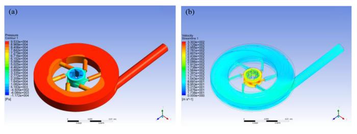
图4
小型化MAS单元驱动气路仿真图. (a)气压分布图;(b)流速分布图
Fig. 4
Simulation diagram of the miniaturized MAS unit drive gas path. (a) Air pressure distribution diagram;(b) Flow velocity distribution diagram
2.3 射频线圈设计与参数优化
本文选用的射频线圈为螺线管线圈,原因是螺线管线圈有以下2点优势:
(1)较好的射频场均匀性
螺线管线圈的轴对称结构使其在轴向产生高度均匀的磁场(与Halbach磁体主磁场方向相适配),根据Biot-Savart定律,有限长螺线管中心区域的磁场均匀性可达90%以上,符合MAS探头对磁场均匀性的严苛要求;
(2)较强的结构适配性
螺线管线圈的电感量可通过匝数灵活调节,且螺线管的圆柱形结构与低场固体MAS探头旋转腔体的几何兼容性高,便于集成高速转子系统.此外,高灵敏度的优势也让螺线管线圈成为低场固体MAS探头的首选线圈.相比之下,亥姆霍兹线圈(线圈半径与高度相等)与平面螺旋线圈因体积或方向限制难以满足需求,考虑到磁场均匀性问题本文也未采用鞍形线圈设计方案[26].
螺线管线圈的尺寸参数包括:线圈直径D,线径d,匝间距s,匝数N,与线圈高度H,其几何结构如图5所示.螺线管线圈的主要指标有信噪比、射频场均匀性和品质因数.
图5

图5
螺线管线圈几何结构图及关键参数示意图
Fig. 5
Geometric structure diagram and key parameters of the solenoid coil
线圈信噪比(SNR)可表示为:
其中,
射频场均匀性可表示为:
其中,
品质因数(Q)可表示为:
其中,
本文选用常用的4 mm直径转子(转子壁厚0.5 mm),兼顾了填充因子和转速要求.根据转子尺寸确定螺线管线圈的基本参数.为了保证较大的填充因子与装样灵活性,螺线管线圈应尽量贴近转子壁,采用线圈直径D=5.2 mm、线径d=1 mm进行设计,此时线圈内孔与转子外壁仅有0.1 mm间隙.此外,为了与小型化MAS单元配合,线圈整体高度不大于10 mm(由于线圈还需要引线,实际高度为9.4 mm).
根据上述参数,使用参数化扫描功能对线圈匝数进行仿真优化,由于线圈的性能与线圈信噪比、射频场均匀性和品质因数成正比,因此,定义线圈综合性能P = SNR×δ均匀×Q,仿真结果如表1所示.
表1 螺线管线圈匝数仿真优化表
Table 1
| 线圈匝数(N) | 相对信噪比(SNR) | 射频场均匀性(δ均匀) | 品质因数(Q) | 综合性能(P) |
|---|---|---|---|---|
| 4 | 3.43E-03 | 59% | 2.89E+02 | 0.586 |
| 5 | 3.68E-03 | 69% | 2.89E+02 | 0.732 |
| 6 | 3.80E-03 | 76% | 2.83E+02 | 0.819 |
| 7 | 3.79E-03 | 80% | 2.70E+02 | 0.815 |
| 8 | 3.65E-03 | 84% | 2.48E+02 | 0.761 |
图6

图6
螺线管线圈B1场分布仿真结果. 其中:磁通密度指射频场磁感应强度,颜色由蓝到红表示磁感应强度由弱到强
Fig. 6
Simulation results of the B1 field distribution of the solenoid coil, where magnetic flux density refers to the magnetic induction intensity of the radio frequency field, and the color from blue to red indicates the magnetic induction intensity from weak to strong
3 探头制作与性能测试
3.1 探头制作
3.1.1 小型化MAS单元制作与测试
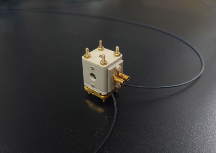
对根据本文设计方案加工的MAS单元零件进行了组装,小型化后整个探头口径缩小至42 mm(其中,MAS单元为27×21 mm2长方体),与传统的4 mm商用MAS探头相比,总体积缩小了约60%.小型化后MAS单元实物图如图7所示.
图7
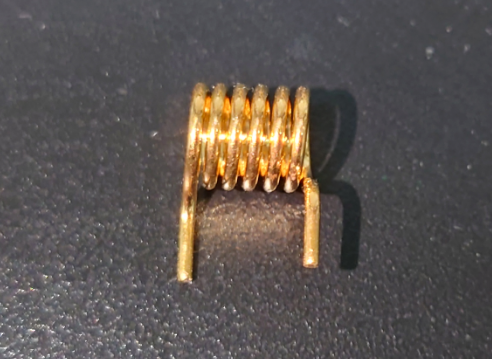
3.1.2 射频线圈制作
为了使射频线圈具有更好的电性能与抗氧化性,线圈加工时采用了无镍镀银镀金工艺,先在紫铜线圈上电镀20 μm厚的银层作为主要导电层,再电镀5 μm金层作为保护层.参数优化后的射频线圈实物图如图8所示.
图8
3.1.3 射频电路制作
实物低场固体MAS探头还包括调谐匹配电路、轴承/驱动气路以及整个探头骨架.其中,调谐匹配电路采用了LC并联谐振网络如图9(a)所示,通过可调电容
图9
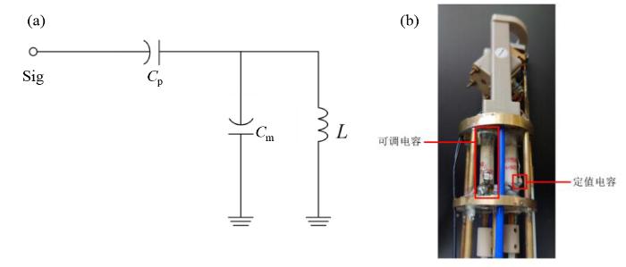
图9
射频电路匹配网络与实物. (a) LC并联谐振网络;(b)射频电路实物图
Fig. 9
Matching network of the radio frequency circuit and the physical picture. (a) LC parallel resonant network; (b) Photograph of the RF circuit
对于一个LC谐振电路,其阻抗与信号频率有关,阻抗最低点称为谐振频率,谐振频率是LC电路的固有属性.谐振频率表示为:
其中,L是等效电路电感,C是调谐电容.在进行探头匹配时,首先对射频线圈电参数进行测试,使用LCR分析仪对射频线圈进行线圈电感、电阻的测试.测得射频线圈电感为260 μH,等效电阻为1.86 Ω.根据上述线圈测试结果与谐振公式,当配以总容值为214 pF的定值电容,则可得到谐振频率为21.35 MHz,满足1H检测.由于可调电容的容值调节范围有限,通过采用定值电容与可调电容相结合的方案,本文研制的射频电路实物如图9(b)所示.
3.1.4 探头的集成
此外,本文为了实现在0.5 T下采集1H和7Li NMR信号,分别研制了1H、7Li两种频率的低场固体MAS探头,探头实物如图10所示.
图10
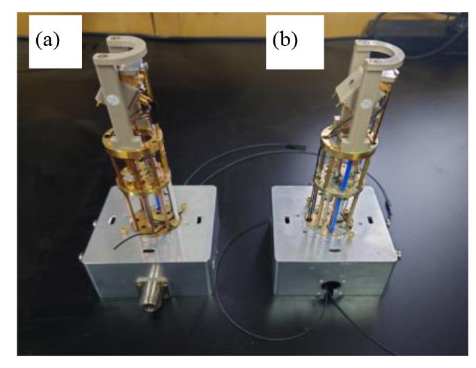
图10
低场固体MAS探头实物图. (a)7Li NMR探头;(b)1H NMR探头
Fig. 10
Physical picture of the low-field solid-state MAS probe. (a) Probe for 7Li NMR signals; (b) Probe for 1H NMR signals
3.2 电性能测试
通过调节低场固体MAS探头底部的旋钮调整可调电容值,使线圈谐振在0.5 T(实际Halbach磁体的场强为0.525 T)下1H、7Li各自的拉莫尔频率(1H为22.35 MHz、7Li为8.69 MHz),并完成50 Ω阻抗匹配. 使用矢量网络分析仪对探头S11参数(用于评估输入端口的匹配程度,反映了信号在该端口的反射情况)进行测试,结果如图11所示.1H、7Li探头的S11分别为-45.21 dB、-22.81 dB,探头的Q值均在30以上,可以实现良好的调谐与匹配.
图11
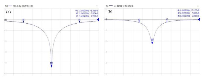
图11
探头S11参数测试结果. (a) 1H探头S11测试结果;(b) 7Li探头S11测试结果
Fig. 11
Test results of the probe S11 parameters. (a) Test results of the S11 parameter for the 1H probe; (b) Test results of the S11 parameter for the 7Li probe
3.3 转速测试
图12
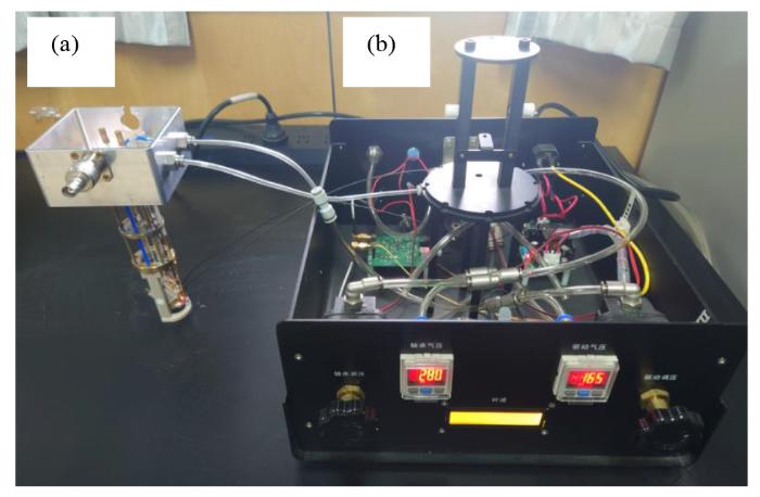
图12
MAS单元转速测试图. (a)低场固体MAS探头;(b)气动控制台
Fig. 12
Rotate speed test diagram of the MAS unit. (a) Low-field solid-state MAS probe; (b) Pneumatic control console
表2 空载转子转速与气压对应表
Table 2
| 实验次数 | 轴承气压/kPa | 驱动气压/kPa | 转速/kHz |
|---|---|---|---|
| 1 | 105 | 35 | 4 |
| 2 | 120 | 45 | 5 |
| 3 | 140 | 55 | 6 |
| 4 | 170 | 70 | 7 |
| 5 | 190 | 85 | 8 |
| 6 | 205 | 100 | 9 |
| 7 | 220 | 120 | 10 |
| 8 | 245 | 145 | 11 |
| 9 | 270 | 165 | 12 |
| 10 | 290 | 190 | 13 |
| 11 | 310 | 215 | 14 |
4 探头的NMR信号测试
4.1 实验平台
图13
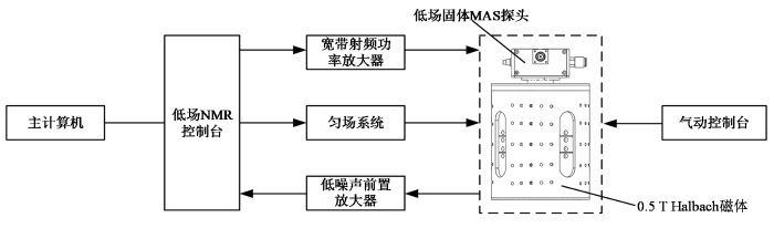
图13
低场核磁共振测试平台组成框图
Fig. 13
Block diagram of the low-field nuclear magnetic resonance testing platform composition
实验测试流程如下:(1)利用装样工具将样品均匀装入MAS转子;(2)根据转速-气压对应表,调节轴承/驱动气压至所需转速;(3)通过可调电容将低场固体MAS探头频率调至中心频率并确保较好的匹配;(4)90˚脉宽测试与匀场操作进行参数优化;(5)采用单脉冲多次累加的方式对样品信号进行检测;(6)测试结束,依次关闭驱动气与轴承气.
4.2 1H NMR测试
首先,选用氢核低场固体MAS探头进行NMR测试,本文采用金刚烷固体粉末(纯度>99%,购于武汉欣申试化工科技有限公司)作为检测样品,将样品装入转子中并插入探头中的MAS单元,然后将低场固体MAS探头置入Halbach磁体中,此时样品正好处于磁体的中心区域,并通过旋转探头位置使主磁场方向与转子呈魔角方向并调节魔角角度调整杆(魔角角度并非固定的,而是需要随时调整,实验场地不平整、探头遭受碰撞或转子在定子腔内的旋转状态不同等各种因素,都会导致魔角角度出现细微偏差.而这细微的魔角偏差往往会对NMR谱图分辨率造成显著影响.为了调节魔角,魔角角度调整杆通常会带有精细螺纹.通过旋转魔角角度调整杆,可以改变整个MAS单元与轴向之间的夹角,从而实现魔角的调节.为了使MAS单元在魔角处保持平衡),在谱仪上实时观察魔角变化情况,对魔角进行精确校准,如图14所示(图14(c)中的
图14
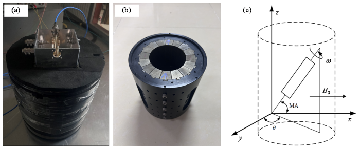
图14
实验时探头与磁体组合图. (a)组合实物图;(b)裸磁体实物图;(c)组合示意图
Fig. 14
Probe and magnet combination diagram. (a) Combined physical diagram; (b) Physical image of a bare magnet; (c) Combination schematic diagram
图15
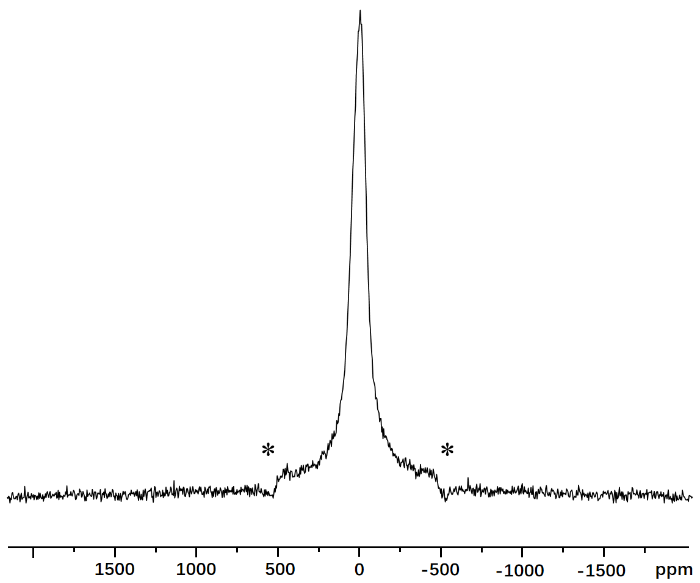
图15
金刚烷样品1H NMR谱图. *为旋转边带
Fig. 15
1H NMR spectra of the adamantane sample. * the rotating sideband
4.3 顺磁样品测试与分析
将装有LiFePO4、Li3PO4、LiCoO2和LiMn2O4粉末(购自武汉欣申试化工科技有限公司,LiFePO4纯度为98%,其余试剂纯度>99%)的转子分别放置在课题组自主研制的LF-NMR谱仪上进行NMR测试.设定谱宽为100 kHz,采用累加次数为100次,转速设置在12 kHz,得到4种样品中的7Li NMR谱如图16所示.图16(a)是文献报道的在Bruker 300 MHz全数字化NMR谱仪和4 mm固体MAS探头、魔角转速为10 kHz下采集的Li3PO4、LiCoO2以及LiMn2O4(800 ℃)样品的7Li NMR谱图[10],图16(b)~(e)分别为使用本文研制的低场MAS探头在0.525 T下采集的LiFePO4、Li3PO4、LiCoO2和LiMn2O4样品的7Li NMR谱图(其中,LiMn2O4的7Li NMR谱图出现2个峰是由于测试时磁场不均匀导致了谱峰分裂).
图16
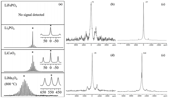
图16
7Li NMR谱图测试结果. (a)文献报道的高场下7Li NMR谱图[10];低场下(b) LiFePO4,(c) Li3PO4,(d) LiCoO2,(e) LiMn2O4的7Li NMR谱图
Fig. 16
Test results of 7Li NMR spectra. (a) 7Li NMR spectrum under high field reported in the literature[10]; 7Li NMR spectrum of LiFePO4 (b), Li3PO4 (c), LiCoO2 (d) and LiMn2O4 (e) under low field
通过对比可知,在300 MHz下各个位点的旋转边带会相互重叠从而产生难以分析的NMR谱,而在低场环境下,由化学位移各向异性、顺磁相互作用引起的自旋边带得到了更有效的抑制,NMR谱图的自旋边带数量相比300 MHz条件下明显减少,显著提高了谱图分辨率.说明本文自研的低场固体MAS探头可以在低场下获得顺磁样品的高分辨率谱图.
5 结论
本文成功研制了一套基于0.5 T Halbach磁体的低场固体MAS探头,通过MAS单元的小型化设计、驱动气路的有限元仿真优化,实现了4 mm转子在14 kHz转速下稳定运行,通过对射频线圈参数的仿真分析及对电路的谐振调试,在12 kHz转速下顺利采集到多种顺磁样品中的7Li NMR信号.实验结果表明低场MAS系统可有效抑制顺磁样品在高场下出现的旋转边带干扰,能够为锂电池正极材料等顺磁体系提供低成本、高精度的分析手段.未来将进一步优化探头灵敏度,拓展其在工业检测与多相材料研究中的应用.
利益冲突
无
参考文献
Materials' methods: NMR in battery research
[J].DOI:10.1021/acs.chemmater.6b03183 URL [本文引用: 1]
Free induction decays of rotating solids
[J].DOI:10.1103/PhysRevLett.2.285 URL [本文引用: 1]
Removal of dipolar broadening of nuclear magnetic resonance spectra of solids by specimen rotation
[J].DOI:10.1038/1831802a0 [本文引用: 1]
A low-cost home-built NMR using Halbach magnet
[J].
DOI:S1090-7807(18)30191-5
PMID:30055440
[本文引用: 1]

The objective of this work is to develop a low-cost compact desktop NMR system based on Halbach magnets with the advantages of small size and ability to generate relatively high field strength. Considering the cost of manufacturing and assembling the magnetic blocks, the system utilized a 3-layer Halbach magnet and a wedge-shaped mechanical structure, which was designed for magnet rapid assembling. The comparison between simulation and calculation results of the initial magnetic field strength distribution showed that design theory and practice were in accordance. The initial homogeneity was 576 ppm in a square with a length of 5 mm. After passive shimming with two magnetic blocks and steel pieces, the uniformity reached 120 ppm in the same area. We developed and tested a compact single board spectrometer with digital modulation and demodulation in order to enhance the system mobility and improve the SNR. A self-made probe was used to carry out experiments with the spectrometer, and the spectral width at half-height reached 20 ppm in a cylinder with a diameter of 1.5 mm and a length of 1 mm. Compact structure and low cost of the system will facilitate and extend the application of desktop NMR system.Copyright © 2018 Elsevier Inc. All rights reserved.
Strong rare earth cobalt quadrupoles
[J].
Cylindrical spinner and speed controller for magicangle spinning nuclear magnetic resonance
[J].
DOI:10.1063/1.1137783
URL
[本文引用: 1]
A new design for a cylindrical spinner suitable for magic angle spinning nuclear magnetic resonance (NMR) is described. The rotor has a large sample volume (0.66 cm3) and is capable of spinning speeds from 500 Hz to 5 kHz at drive gas pressures below 50 lb/in.2. The rotor is completely supported by gas bearings. Axial positioning is provided by the rotor’s T shape, leaving the bottom surface available for a photoelectric tachometer. The coil is wrapped on a form machined into the outer surface of the stator, producing a high filling factor. Also described is an instrument which controls the spinning speed of such a rotor to ±0.6 Hz around a set speed in the range of 3–4 kHz. The rotor’s speed is determined by means of a photoelectric tachometer. The instrument then compares this measured speed to the desired value and adjusts the gas flow to the rotor to correct any difference.
Magic-angle spinning solid-state multinuclear NMR on low-field instrumentation
[J].
DOI:10.1016/j.jmr.2013.10.015
PMID:24291330
[本文引用: 1]
Mobile and cost-effective NMR spectroscopy exploiting low-field permanent magnets is a field of tremendous development with obvious applications for arrayed large scale analysis, field work, and industrial screening. So far such demonstrations have concentrated on relaxation measurements and lately high-resolution liquid-state NMR applications. With high-resolution solid-state NMR spectroscopy being increasingly important in a broad variety of applications, we here introduce low-field magic-angle spinning (MAS) solid-state multinuclear NMR based on a commercial ACT 0.45 T 62 mm bore Halbach magnet along with a homebuilt FPGA digital NMR console, amplifiers, and a modified standard 45 mm wide MAS probe for 7 mm rotors. To illustrate the performance of the instrument and address cases where the low magnetic field may offer complementarity to high-field NMR experiments, we demonstrate applications for (23)Na MAS NMR with enhanced second-order quadrupolar coupling effects and (31)P MAS NMR where reduced influence from chemical shift anisotropy at low field may facilitate determination of heteronuclear dipole-dipole couplings.Copyright © 2013 Elsevier Inc. All rights reserved.
High resolution solid state NMR in paramagnetic metal-organic frameworks
[J].DOI:10.1016/j.ssnmr.2022.101811 URL [本文引用: 1]
High resolution solid-state NMR on the desktop
[J].DOI:10.1016/j.ssnmr.2023.101884 URL [本文引用: 4]
High resolution mas NMR of solids by a routine spectrometer for liquids
[J].
Advances in the application of high-resolution magic-angle spinning NMR spectroscopy
[J].
Continuous cell separation using novel magnetic quadrupole flow sorter
[J].DOI:10.1016/S0304-8853(98)00581-2 URL [本文引用: 1]
Unified view of magnetic nanoparticle separation under magnetophoresis
[J].
DOI:10.1021/acs.langmuir.0c00839
PMID:32551702
[本文引用: 1]
The migration process of magnetic nanoparticles and colloids in solution under the influence of magnetic field gradients, which is also known as magnetophoresis, is an essential step in the separation technology used in various biomedical and engineering applications. Many works have demonstrated that in specific situations, separation can be performed easily with the weak magnetic field gradients created by permanent magnets, a process known as low-gradient magnetic separation (LGMS). Due to the level of complexity involved, it is not possible to understand the observed kinetics of LGMS within the classical view of magnetophoresis. Our experimental and theoretical investigations in the last years unravelled the existence of two novel physical effects that speed up the magnetophoresis kinetics and explain the observed feasibility of LGMS. Those two effects are (i) cooperative magnetophoresis (due to the cooperative motion of strongly interacting particles) and (ii) magnetophoresis-induced convection (fluid dynamics instability originating from inhomogeneous magnetic gradients). In this feature article, we present a unified view of magnetophoresis based on the extensive research done on these effects. We present the physical basis of each effect and also propose a classification of magnetophoresis into four distinct regimes. This classification is based on the range of values of two dimensionless quantities, namely, aggregation parameter * and magnetic Grashof number, which include all of the dependency of LGMS on various physical parameters (such as particle properties, thermodynamic parameters, fluid properties, and magnetic field properties). This analysis provides a holistic view of the classification of transport mechanisms in LGMS, which could be particularly useful in the design of magnetic separators for engineering applications.
Inhomogeneous interactions of solids under MAS
[J].DOI:10.7498/aps URL [本文引用: 1]
魔角旋转情形下固体的非均匀相互作用
[J].
Aspects of NMR reciprocity and applications in highly conductive media
[J].
DNP CP/MAS probe design and discussion of DNP experimental technique
[J].
固体高分辨DNP CP/MAS探头的研制及DNP实验技术的探讨
[J].介绍了自行研制的用于动态核极化实验的固体高分辨CP/MAS探头,给出了典型含自由基固体样品的DNP增强高分辨NMR谱.并对动态核极化实验中的技术问题进行了讨论,提出了相应的解决方法.
Magic-angle spinning: a historical perspective
[J].DOI:10.1007/b98646 PMID:22160286 [本文引用: 1]
A method of orienting the rotation axis of a spinning sample used in a nuclear magnetic resonance experiment, its synthesis and use: EP, 0051124B1
[P]. 1984-12-05.
Device and method for spinning a sample for NMR probes, its synthesis and use: EP, 0020085A1
[P]. 1980-12-10.
High speed spinner for NMR spectrometer, its synthesis and use: EP, 0249383B1
[P]. 1991-01-16.
Four millimeter spherical rotors spinning at 28 kHz with double-saddle coils for cross polarization NMR
[J].DOI:10.1016/j.jmr.2019.03.006 URL [本文引用: 1]
A miniaturised NMR RF probe design with external field-locking channel
[J].
一种带外部锁场通道的小型化核磁共振射频探头设计
[J].
DOI:10.11938/cjmr20223044
[本文引用: 2]
温度漂移是影响桌面式核磁共振波谱仪测量精度的一个重要因素,在探头中添加锁场线圈实现场频联锁是抑制温度漂移的常用手段.本文基于实验室紧凑型Halbach磁体,设计了一套带有外部锁场功能的双通道探头.针对目标区域,使用COMSOL仿真对比了螺线管线圈、鞍形线圈和亥姆霍兹线圈的磁场均匀性、信噪比和品质因数,发现螺线管线圈具有最佳综合性能.进一步针对螺线管线圈结构,对线圈直径、高度、匝数、匝间距以及漆包线半径进行了仿真优化,得到漆包线半径为0.4 mm、线圈直径和高度为8.2 mm、匝间距为1.6 mm、匝数为5是最优螺线管尺寸.基于仿真结果,制作了探头实物,并配合外围电路进行测试.结果表明,两个线圈通道之间串扰较小,信号检测通道信噪比达到50以上,锁场通道信噪比达到20以上.锁场实验结果表明,添加锁场后整体系统的频率漂移约为0.2 ppm/h(1 ppm=10<sup>-6</sup>),验证了此探头设计可用于基于紧凑型Halbach磁体的磁共振设备.
Efficient stator/rotor assembly for magic-angle spinning NMR
[J].
DOI:10.1063/1.1139626
URL
[本文引用: 1]
A newly designed stator assembly for cylindrical spinners used in magic-angle spinning nuclear-magnetic-resonance experiments is described. Separate driving and bearing gas chambers allow variable and stable spinning speeds, and this design permits easy starting and stopping of the rotor. Isolation of the chambers is achieved with the application of pressure screws rather than O rings or glue lines to avoid leakage at high gas pressures. The overall dimensions are optimal to facilitate easy assembly. Some significant modifications have been made to an earlier spinner design. These improvements give better efficiency and concentricity of the spinner. Applications are illustrated with carbon-13 cross polarization/magic angle spinning (CP/MAS) spectra carried out at different rotor spinning rates.
